Create a Continuous Alarm
Create a Continuous Alarm
You want to set up a management station alarm that monitors a value (for example, > 87).
- You have the appropriate user rights to create an alarm.
- In System Browser, select Project > Field Networks > [network] > Hardware > [device] > [data point].
NOTE: The folder path may vary by subsystem or selected view. - Select the Object Configurator tab.
- In the Properties expander, select the appropriate property (for example, Present_Value).
- In the Alarm Configuration expander, select the Valid check box to display activation in grey.
- Select the Management Station option.
- (Optional) From the Alarm flags drop-down-list, select None, No alarm on driver invalid, No alarm on source time invalid (for background information, see the alarm configuration reference section).
- In the Alarm kind drop-down list, select Continuous.
- Click New to define a new alarm class.
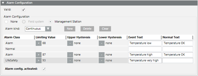
- Define the corresponding conditions for each alarm class:
a. Select the Alarm Classtype.
b. In the Limiting Value column, select the operand.
c. In the Limiting Value column, select the value.
d.(Optional) Enter the value in the Upper Hysteresis and/or Lower Hysteresis columns. Entering a hysteresis prevents the triggering of an alarm each time there is a slight variation.
e. Enter the necessary information in the Event Text field and Normal Text field. Depending on your assigned event profile, the alarm lamps maybe different as in the picture.
f. Select the Alarm config. activated check box. - Click Save
 .
.

The limit values are only monitored when the following conditions are met:
- In the Alarm Configuration expander, the Alarm config. activated check box is selected.
- In the Main expander, the Out of scan check box is deselected.
- The entries are saved.
Functionality of Hysteresis
The alarm triggers according to the set threshold value if a Upper Hysteresis and LowerHysteresis entered on the selected setpoint. Hysteresis allows the user to incorporate tolerance in the alarm levels. In the following image, hysteresis is used to define the alarm conditions.
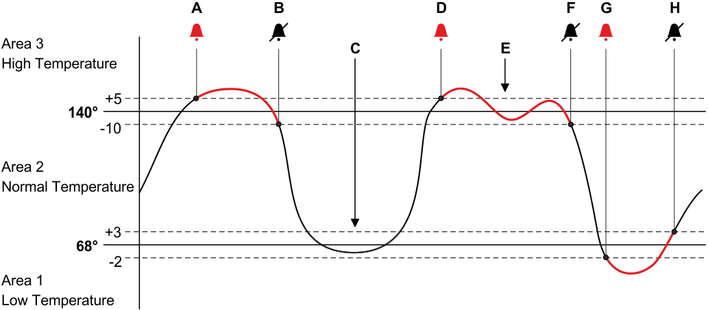
Explanation of Hysteresis Behavior | |
| Description |
A | The point goes into alarm because the value has crossed the Upper Hysteresis of the High Temperature alarm. |
B | The point returns to normal because the value has returned to Normal Temperature. |
C | Notice that the point did not go into alarm as it reached a value lower than the Low Temperature value. Because it did not cross the Lower Hysteresis, it did not trigger the alarm. |
D | The point goes into alarm because, again, the value has crossed the Upper Hysteresis of the High Temperature alarm. |
E | Notice that the point did not come out of alarm as it fluctuated. It remained in alarm until it crossed the Lower Hysteresis. |
F | The point returns to normal because the value has returned to the Normal Temperature condition. |
G | The point goes into alarm because the value has crossed the Lower Hysteresis of the Low Temperature alarm. |
H | The point returns to normal because the value has returned to the Normal Temperature condition. |
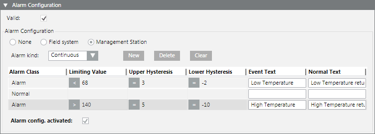
Entry of alarm configuration for an alarm high and low:
Supported Operands | ||
Operand | Meaning | Example |
> | Greater than |
|
< | Less than |
|
>= | Greater than or equal to |
|
<= | Less than or equal to |
|


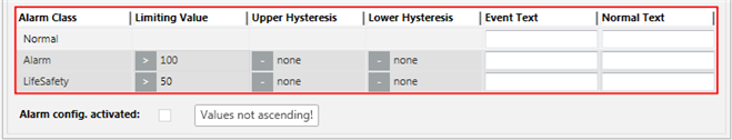
Fault indication
- The value sequence is not ascending. A valid value must be less than 50.
Example: Advanced Temperature Monitoring
You can easily create an advanced temperature monitor by selecting the temperature sensor (Present_Value) in System Browser. Define a corresponding message for each temperature limit. The corresponding message is sent out when the set values are reached. Use the Hysteresis columns to avoid triggering additional messages for slight temperature deviations.
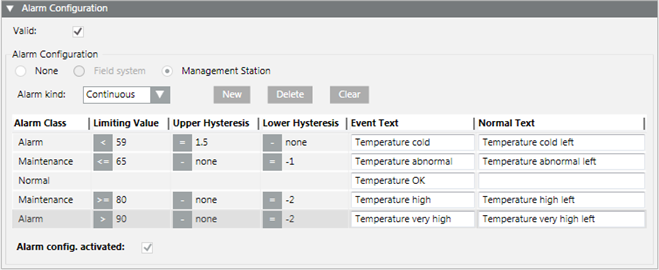
You can define only one normal range. First, create the corresponding number of alarm classes and then select the corresponding position for normal range.